128T Pi-Blaster
or
How to install an 128T SSR on a BareMetal Server via PXE-Boot from a Raspberry Pi
Version: 1.0
Last edit: 31 March 2021
Copyright: Copyright (c) [2021], Hartmut Schroeder All rights reserved.
Notice and Disclaimer: This code is licensed to you under the Creative Commons Attribution Share Alike 3.0 (the “License”). You may not use this code except in compliance with the License. You can obtain a copy of the License at http://spdx.org/licenses/CC-BY-SA-3.0
Third-Party Code: This code may depend on other components under separate copyright notice and license terms. Your use of the source code for those components is subject to the terms and conditions of the respective license as noted in the Third-Party source code file.
Warning
Please make yourself aware of the documentation conventions used in this document:
Used CLI color code conventions in this documentation are:
Black  = Normal list output the system did in response to a command (default)
Green  = CLI Input and configuration pieces to use Copy&Paste
Purple = Variable pieces of the configuration you need to adapt for your lab
Red    = Something to look at or warn you about
A deeper documentation about the color-schemas and how this document was created can be found at https://github.com/Juniper/lab-doc-convert
1. Motivation
The idea is based on the original 128T Blaster-Project https://github.com/128technology/blaster as a reference. It doesn’t use any code from the original project but has some similarities with it still because the way you want to PXE boot a new system is always the same.
The “Server” to provision a new Router is the famous Raspberry Pi. Using the Raspberry PI has the following advantages to us:
It’s a <100.-USD cheap Platform that is worldwide avail and has enough horsepower for all needed tasks.
Using the Raspberry Pi Version 4 we can use the TinyPilot-Project to remotely control the Keyboard and capture the Video of the target System that we want to provision. This is our way to change / control the BIOS remotely without IPMI in place!
Instead of using it only at Home or in a Lab we can send this also to a remote site to provision the hardware right there where it is deployed or later used.
With the Raspberry Pi as platform we dedicate the Ethernet Interface of it to provide special DHCP-Leases to the local attached Server. It is assumed the Raspberry Pi has a Wi-Fi connection that enables him to get to the Internet. The Raspberry Pi will be the Router towards the Internet for the systems attached to his local Ethernet-Interface. The DHCP-Lease to the local server will cause a PBX-Boot with remote OS-install via a Centos Anaconda Kickstart process. In contrast to the original Blaster project we always install a vanilla Centos V7.5 build and not a special 128T ISO. During the OS installation we create a script locally that on the first boot of the system after it reboots from the OS Provision runs the 128T installer getting all need packages and update from the original public 128T YUM-Repo Server. After the 128T software installation has finished the system reboots again now being able to contact the 128T conductor for further instructions. You can call this a real Zero-Touch-Provision method. The whole process for a single system is typically below 30minutes before you can manage it from the 128T conductor.
Furthermore, the following is supported:
You can provision multiple systems at the same time (but remote Keyboard/Video needs to be switched by someone local still).
Each time you provision or re-provision a system it will automatically get a new Router-name that will be seen as a new Asset-ID on the Conductor.
During the OS-Installation we automatically collect information about the system we provision (such as the PCI-ID’s of the Ethernet-Interfaces) and send it to the Raspberry Pi to be used later.
Apart from legacy PXE and regular UEFI PXE we also support the new UEFI V2.5 http-PXE method which doesn’t need any local TFTP-Server anymore.
Each time you provision you always get the latest/greatest Firmware for your 128T Router. (You can change the provision.json File if you want a specific code).
Note
Last but not least, Raspberry Fanboys like me need some cool stuff to do on their weekend. :-)
2. What do you need for this Project?
The Kit-List for this project is rather simple. At a minimum you need:
Plain Internet Access via Wi-Fi for the Raspberry Pi and the system behind it. A normal local Broadband Router will do. If you are somewhere remote consider the Hotspot-Function of a Smartphone.
A Raspberry Pi 4 with and 4GB RAM or higher. (older Raspberry’s models won’t support TinyPilot and have slow Ethernet).
>=16GB Micro SD-Card as Storage for the Raspberry Pi.
A Power-Supply for the Raspberry Pi (read chapter 5.2 before you purchase)
A target Router/server which you want to provision (well that’s obvious)
An Ethernet Patch-cable between Raspberry Pi and Router
For the TinyPilot option you additionally need:
A HDMI-Frame grabber supported by the TinyPilot-Project. Those typically cost around 20.-USD and come from various sources. Try to get one with a MacroSilicon MS2109-Chip inside as this is best price/value as of now.
An HDMI-Cable between Frame-Grabber and system we want to provision.
A special USB OTG-Cable to power the Raspberry Pi while using the USB-C connector same time to emulate a Keyboard towards the system:
Order one of the options offered by the TinyPilot Project if you are afraid to solder something yourself.
Do it yourself following the instructions given in chapter 5.2
For the 128T SSR from Juniper Networks you need:
A Certificate/Key to be able to download the Software from the public YUM-Repo-Server.
Official Licenses for the system you want to provision.
Minimum of one installed 128T Conductor with a known IP-Address the Router can send messages to later and you can take over control then.
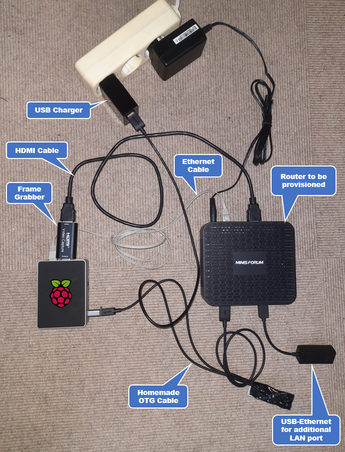
Once you have everything wire it similar to my home-lab and then you can start the fun.
3. Building it
Following these instructions, you are hopefully able to build a system together similar to mine and have the same success. Let’s start it:
3.1. Preparing the Raspberry Pi
We’ve just used a Raspian-Lite build like 2021-01-11-raspios-buster-armhf-lite as we don’t need a Desktop for the Pi. You should know how that works and if now google that I’m not explaining the process here. The below is just a reminder for me what to put onto the boot-stick before I put the Micro SD-Card into the Pi.
##### onto / of the Micro SD-Card

touch ssh

vi wpa_supplicant.conf
ctrl_interface=DIR=/var/run/wpa_supplicant GROUP=netdev
update_config=1
country=DE

network={
        ssid="myssid"
        psk="mypsk"
}
For all futher tasks we assume you figured the IP-Address the Raspberry Pi got on your network via Wi-Fi to access it via SSH.
3.2. Create eth0-config and SNAT to WLAN
First, we configure the Ethernet-Interface. Do not change the eth0 IP-Address 192.168.10.9 as it’s referenced multiple times in this document in other places. We also add some IP-Tables code to /etc/rc.local that each time the Raspberry Pi boot activates Kernel forwarding between eth0 and Wi-Fi while also applying Source-NAT on the Wi-Fi for all traffic from eth0. This shields the eth0 attached devices and DHCP-Server from your home/lab while at the same time providing Internet Access same as you Raspberry Pi should have via Wi-Fi. After we’ve done all this we reboot the Raspberry Pi to get this forwarding activated.
ssh pi@192.168.1.117

sudo -i

id
uid=0(root) gid=0(root) groups=0(root)

cd /root

apt-get update

cat <<EOF >/etc/network/interfaces
auto lo
iface lo inet loopback

auto eth0
allow-hotplug eth0
iface eth0 inet static
address 192.168.10.9
netmask 255.255.255.0
dns-nameservers 8.8.8.8

auto wlan0
allow-hotplug wlan0
iface wlan0 inet dhcp
wpa-conf /etc/wpa_supplicant/wpa_supplicant.conf
iface default inet dhcp
EOF


cat <<EOF >/etc/rc.local
#!/bin/sh -e
#
# rc.local
#
echo "Enable Kernel forwarding between Interfaces (Router mode)"
echo 1 > /proc/sys/net/ipv4/ip_forward
echo "Enable NAT on wlan0 and forwarding between eth0 <-> wlan0"
/sbin/iptables -t nat -A POSTROUTING -o wlan0 -j MASQUERADE
/sbin/iptables -A FORWARD -i wlan0 -o eth0 -m state --state RELATED,ESTABLISHED -j ACCEPT
/sbin/iptables -A FORWARD -i eth0 -o wlan0 -j ACCEPT

exit 0
EOF

reboot
3.3. Create TFTP Server
Here we create a local TFTP-Server that is usually only used to provide the PXE-Boot images and instruction to the systems. In our case we can also upload files which we use to get information about the systems we provisioned.
ssh pi@192.168.1.117

sudo -i

id
uid=0(root) gid=0(root) groups=0(root)

cd /root

apt-get install -y tftpd-hpa inetutils-inetd tcpdump

mkdir -p /tftp/secure-boot

cat <<EOF >>/etc/default/tftpd-hpa
# /etc/default/tftpd-hpa

TFTP_USERNAME="tftp"
TFTP_DIRECTORY="/tftp"
TFTP_ADDRESS="0.0.0.0:69"
TFTP_OPTIONS="--secure -c -vvv"
RUN_DAEMON="yes"
OPTIONS="-l -vvv"
EOF

chown -R tftp /tftp
service tftpd-hpa restart

netstat -tunap | grep tftp
udp        0      0 0.0.0.0:69              0.0.0.0:*                           3524/in.tftpd                          3196/in.tftpd
3.4. Download needed Centos 7.5 iso-image and copy content
Next, we need to download and extract the vanilla cento V7.5 image from the internet.
wget https://mirrors.oit.uci.edu/centos/7.5.1804/isos/x86_64/CentOS-7-x86_64-Minimal-1804.iso

md5sum CentOS-7-x86_64-Minimal-1804.iso
fabdc67ff3a1674a489953effa285dfd  CentOS-7-x86_64-Minimal-1804.iso

mount -o loop,ro CentOS-7-x86_64-Minimal-1804.iso /mnt
mkdir -p /media/cdrom
cp -r /mnt/* /media/cdrom
umount /mnt
3.5. Using IPXE as PXE-Loader
IPXE is in general the best and most flexible option to provide any PXE boot-code to any local system and then put the host OS on it. This was the only way we found to support PXE over HTTP (UEFI V2.5) as some newer BIOS’s seem to support this option only.
Here are some (sorry German) Project that we re-viewed and used their instructions.
# https://daimonmicha.bplaced.net/vernetzung/pxe-boot-mit-ipxe.html
# https://www.linux-magazin.de/ausgaben/2014/08/i-pxe/2/
3.5.1. Build ipxe files on Intel-Platform
We did not find a way to build the IPXE-Loaders on the Raspberry Pi itself. Maybe there is but we need to build Intel Code so we did this section on a WSL2 Ubuntu 20.04 image on a Windows 10 PC. You may choose similar or a VM somewhere. It’s up to you.
Warning
You don’t need to build these files. We have attached the ones created as embedded File below. As long as you don’t change the eth0 IP-Address of the Raspberry Pi from 192.168.10.9 to something else you should be good.
DOWNLOAD ipxe-files-build-for-internal-webserver.tgz
For those wanting you change something here are the instructions on how to build this code.
apt-get install -y git build-essential syslinux liblzma-dev
# yum install -y xz-devel

git clone http://git.ipxe.org/ipxe.git
cd ipxe/src

cat <<EOF >chain.ipxe
#!ipxe

#prompt --key 0x02 --timeout 5000 Press Ctrl-B for the iPXE command line... && shell ||

dhcp
chain http://192.168.10.9:8888/boot/net.ipxe
EOF

make
make bin/ipxe.pxe EMBED=chain.ipxe
#make bin/ipxe.usb EMBED=chain.ipxe
make bin-x86_64-efi/ipxe.efi EMBED=chain.ipxe
make bin-i386-efi/ipxe.efi EMBED=chain.ipxe

cp bin/ipxe.pxe ../../ipxe.pxe
cp bin-x86_64-efi/ipxe.efi ../../ipxe.x86_64.efi
cp bin-i386-efi/ipxe.efi ../../ipxe.i386.efi
cd ../..

ls -l ipxe.*
-rw-r--r-- 1 root root 911648 Mar  4 12:23 ipxe.i386.efi
-rw-r--r-- 1 root root 331482 Mar  4 13:04 ipxe.pxe
-rw-r--r-- 1 root root 991264 Mar  4 12:23 ipxe.x86_64.efi
Note
Transfer these 3 files to the /root directory of your Raspberry Pi
3.6. Using syslinux bootloaders
Unfortunately we found that some platforms do not work with the UEFI Ipxe loader. They can’t figure out the Network interface for some reason. No clue what that is. The original 128T Blaster Project uses syslinux. We tested that and found the same issue appears when you use a regular stable syslinux V6.03 build BUT the issue was gone when we then used a beta build of syslinux V6.04! Because if this strange issue you will see that we build a hybrid using ipxe for legacy-PXE and the new PXE-over-HTTP option and then syslinux beta 6.04 to solve the issue with some UEFI systems. Not nice but it counts that is works in the end.
wget https://cdn.kernel.org/pub/linux/utils/boot/syslinux/Testing/6.04/syslinux-6.04-pre1.tar.gz

tar xfz syslinux-6.04-pre1.tar.gz

cp syslinux-6.04-pre1/bios/core/pxelinux.0 /tftp
cp syslinux-6.04-pre1/bios/com32/libutil/libutil.c32 /tftp
cp syslinux-6.04-pre1/bios/com32/elflink/ldlinux/ldlinux.c32 /tftp
cp syslinux-6.04-pre1/efi32/efi/syslinux.efi /tftp/syslinux32.efi
cp syslinux-6.04-pre1/efi32/com32/elflink/ldlinux/ldlinux.e32 /tftp/ldlinux.e32
cp syslinux-6.04-pre1/efi64/com32/menu/menu.c32 /tftp
cp syslinux-6.04-pre1/efi64/efi/syslinux.efi /tftp/syslinux64.efi
cp syslinux-6.04-pre1/efi64/com32/elflink/ldlinux/ldlinux.e64 /tftp/ldlinux.e64

# to be able to support legacy clients
mkdir -p /tftp/secure-boot
cp /media/cdrom/images/pxeboot/vmlinuz /tftp/secure-boot
cp /media/cdrom/images/pxeboot/initrd.img /tftp/secure-boot

# CHANGE first line "default linuxuefi" OR "default linuxlegacy"

mkdir -p /tftp/pxelinux.cfg

cat <<EOF >/tftp/pxelinux.cfg/default
default linuxuefi

LABEL linuxuefi
  MENU DEFAULT
  MENU LABEL Boot via UEFI Loader
  KERNEL http://192.168.10.9:8888/images/pxeboot/vmlinuz
  APPEND initrd=http://192.168.10.9:8888/images/pxeboot/initrd.img ip=dhcp inst.repo=http://192.168.10.9:8888 ks=http://192.168.10.9:8888/cgi-bin/kickstart.py

LABEL linuxlegacy
  MENU LABEL Boot via LEGACY Loader
  KERNEL secure-boot/vmlinuz
  APPEND initrd=secure-boot/initrd.img ip=dhcp inst.repo=http://192.168.10.9:8888 ks=http://192.168.10.9:8888/cgi-bin/kickstart.py
EOF
3.7. Installing TinyPilot
Installing TinyPilot is cute and worked for me out of the Box via the script provided by the Project. Plug-in the Frame grabber (otg-cable can be attached later) and then start the script and reboot the Raspberry Pi after it.
v4l2-ctl --list-devices
bcm2835-codec-decode (platform:bcm2835-codec):
        /dev/video10
        /dev/video11
        /dev/video12

bcm2835-isp (platform:bcm2835-isp):
        /dev/video13
        /dev/video14
        /dev/video15
        /dev/video16

UVC Camera (534d:2109): USB Vid (usb-0000:01:00.0-1.1):
        /dev/video0
        /dev/video1

#ffmpeg \
#  -re \
#  -f v4l2 \
#  -i /dev/video0 \
#  -vcodec libx264 \
#  -f mpegts udp://192.168.1.117:1234/stream

#
# Install Tinypilot https://github.com/mtlynch/tinypilot
# https://mtlynch.io/key-mime-pi/
#

curl -sS https://raw.githubusercontent.com/mtlynch/tinypilot/master/quick-install \
  | bash -

reboot
3.8. Create Kickstart cgi-bin for nginx webserver
After the TinyPilot Project is installed we now have a nginx webserver locally on the system that we can re-use for other proposes. For us it provides access to the original files from the Centos*.ISO that are now copied to /media/cdrom . So we create a new site to access those Files plus a directory to use own cgi-scripts.
ssh pi@192.168.1.117

sudo -i

id
uid=0(root) gid=0(root) groups=0(root)

apt-get install -y fcgiwrap

cat <<EOF >/etc/nginx/sites-enabled/cdrom.conf

server {

    listen 8888 default_server;

    server_name cdrom;

    root /media/cdrom;

    index index.html;

    proxy_buffers 16 16k;
    proxy_buffer_size 16k;
    proxy_set_header Host \$host;
    proxy_set_header X-Forwarded-For \$proxy_add_x_forwarded_for;
    proxy_http_version 1.1;


    location / {
      autoindex on;
    }

    location /cgi-bin/ {
      gzip off;
      rewrite ^/cgi-bin/(.*)\.cgi /$1.cgi break;

      fastcgi_pass  unix:/var/run/fcgiwrap.socket;
      include /etc/nginx/fastcgi_params;
      fastcgi_param SCRIPT_FILENAME  /media/cdrom/\$fastcgi_script_name;
    }

}
EOF
We now test the server and the cgi-script capability as below.
mkdir -p /media/cdrom/cgi-bin

cat <<EOF >/media/cdrom/cgi-bin/kickstart.py
#!/usr/bin/python3
print('Content-Type: text/plain')
print('')
print('This is my test!')
EOF

chmod 755 /media/cdrom/cgi-bin/kickstart.py

service nginx restart

curl http://192.168.10.9:8888/cgi-bin/kickstart.py
This is my test!

netstat -tunap | grep 80
tcp        0      0 0.0.0.0:80              0.0.0.0:*               LISTEN      764/nginx: master p
tcp        0      0 127.0.0.1:8000          0.0.0.0:*               LISTEN      818/python
tcp        0      0 127.0.0.1:8001          0.0.0.0:*               LISTEN      742/ustreamer

netstat -tunap | grep 8888
tcp        0      0 0.0.0.0:8888            0.0.0.0:*               LISTEN      931/nginx: master p
If this is ok we install the yaml and jinja2 support for python and create the final cgi-script to render our kickstart file that defines what is installed and how on the system via the Centos anaconda installer.
apt-get install -y python3-yaml python3-jinja2

cat <<EOF >/media/cdrom/cgi-bin/kickstart.py
#!/usr/bin/python3
import yaml
from jinja2 import Environment, FileSystemLoader

# Load the data from the YAML file into a Python Dictionary
with open(r'/media/cdrom/cgi-bin/kickstart.yml') as file:
    config_data  = yaml.safe_load(file)
#print(config_data)

# increment installnumber
config_data['installnumber'] = config_data['installnumber'] + 1
# write back to yaml for next installation
file = open("/media/cdrom/cgi-bin/kickstart.yml", "w")
yaml.dump(config_data, file, default_flow_style=False)
file.close()

# Pass the directory containing the template to the FileSystemLoader
# Load the environment with the relative templates directory set and strip whitespace
env = Environment(loader = FileSystemLoader('/media/cdrom/cgi-bin'), trim_blocks=True, lstrip_blocks=True)

# Load the kickstart configuration template into the environment
template = env.get_template('kickstart.j2')

# Render the merged configuration by passing in the config_data dictionary
output = template.render(config_data)
# Print the rendered configuration to the screen
print('Content-Type: text/plain')
print('')
print(output)
EOF
Now we create a small yaml-file containing the install number that is incremented with each system build, plus the root/admin Passwords and the Conductor IP to contact after the 128T Software installer finischd the installation.
Warning
Be sure to change the values for the root and admin account passwords and adapt the conductor IP-Address to your own.
cat <<EOF >/media/cdrom/cgi-bin/kickstart.yml
installnumber: 1
routername: "router"
nodename: "node1"
conductorip: "192.168.1.7"
adminpass: "Juniper123!"
rootpass: "juniper123"
EOF

# IMPORTANT to allow cgi-script to update yml-file
chown www-data:www-data /media/cdrom/cgi-bin/kickstart.yml

cat <<EOF >/media/cdrom/cgi-bin/kickstart.j2
This is just another test {{ nodename }}.{{ routername }}{{ installnumber }}
EOF

chmod 755 /media/cdrom/cgi-bin/kickstart.py
chown www-data:www-data /media/cdrom/cgi-bin/kickstart.py

service nginx restart

ls -l /media/cdrom/cgi-bin
total 24
-rw-r--r-- 1 root     root     9409 Mar  3 11:33 kickstart.j2
-rwxr-xr-x 1 www-data www-data 1110 Mar  3 11:11 kickstart.py
-rw-r--r-- 1 www-data www-data  216 Mar  3 11:34 kickstart.yml

# let us test our script again
curl http://192.168.10.9:8888/cgi-bin/kickstart.py
This is just another test node1.router2

curl http://192.168.10.9:8888/cgi-bin/kickstart.py
This is just another test node1.router3

curl http://192.168.10.9:8888/cgi-bin/kickstart.py
This is just another test node1.router4

# you see the yaml changes
cat /media/cdrom/cgi-bin/kickstart.yml
adminpass: Juniper123!
conductorip: 192.168.1.7
installnumber: 4
nodename: node1
rootpass: juniper123
routername: router
As you see in the above example each time you access the kickstart.py on the webserver the name of the future router will be templated and incremented! This is important to understand as it will also be your Asset-ID’s on the conductor when you try to manage the router.
3.9. Install and configure the DHCP-Server
In this step we install a configure a local DHCP-Server for the eth0-interface of the Raspberry Pi. It will constantly instruct all DHCP-Clients when they obtain a Lease to PXE-Boot and install Centos V7.5 to stop ending up in an endless installation loop you either modify the DHCP-Server config when you see the message in the access log of the webserver (explained below in chapter 4.1) or you use TinyPilot to just instruct the systems BIOS to attempt PXE-Boot only one time.
As explained above in chapter 3.6 due to some issues we found this is a hybrid of using Ipxe and syslinux to boot the system and then starting the installation. If you don’t see similar issues you can also use ipxe for regular UEFI installations using ipxe.
apt-get install -y isc-dhcp-server

cp /etc/dhcp/dhcpd.conf /etc/dhcp/dhcpd.conf.orig
mv /etc/dhcp/dhcpd6.conf /etc/dhcp/dhcpd6.conf.orig

cat <<EOF >/etc/dhcp/dhcpd.conf
ddns-update-style none;
default-lease-time 600;
max-lease-time 7200;
option arch code 93 = unsigned integer 16;
authoritative;

log-facility local7;

subnet 192.168.10.0 netmask 255.255.255.0 {
  range 192.168.10.100 192.168.10.199;
  option domain-name-servers 8.8.8.8;
  option subnet-mask 255.255.255.0;
  option routers 192.168.10.9;
  default-lease-time 600;
  max-lease-time 7200;

  class "Legacy" { # Intel X86 PC (PC BIOS)
    match if substring(option vendor-class-identifier, 0, 20) = "PXEClient:Arch:00000";
    filename "ipxe.pxe";
  }
  class "UEFI-32-6" { # UEFI - IA32
    match if substring(option vendor-class-identifier, 0, 20) = "PXEClient:Arch:00006";
    filename "ipxe32.efi";
  }
  class "UEFI-64-1" { # UEFI - Byte Code
    match if substring(option vendor-class-identifier, 0, 20) = "PXEClient:Arch:00007";
# we use syslinux 6.04-pre1! instead of ipxe
# because of some strange platform issues
     next-server 192.168.10.9;
     filename "syslinux64.efi";
# here is the original ipxe activation line
#    filename "ipxe64.efi";
  }
  class "UEFI-64-x86" { # UEFI - x86-64
    match if substring(option vendor-class-identifier, 0, 20) = "PXEClient:Arch:00009";
    filename "ipxe64.efi";
  }
  class "httpclients" { # UEFI v2.5 HHTP-Client
    match if substring (option vendor-class-identifier, 0, 10) = "HTTPClient";
    option vendor-class-identifier "HTTPClient";
    filename "http://192.168.10.9:8888/boot/ipxe64.efi";
  }
}
EOF
We experienced some issues with the dhcp-server installation that may also happen to you. Use the below instructions to fix those.
ps aux | grep dhcpd
root       772  0.0  0.1  10164  6880 ?        Ss   18:52   0:00 /usr/sbin/dhcpd -4 -q -cf /etc/dhcp/dhcpd.conf
root       859  0.0  0.0   7348   552 pts/0    S+   18:54   0:00 grep dhcpd

kill -9 772
rm -f /var/run/dhcpd.pid

mv /etc/default/isc-dhcp-server /etc/default/isc-dhcp-server.orig

cat <<EOF >/etc/default/isc-dhcp-server
INTERFACESv4="eth0"
EOF

service isc-dhcp-server restart

# tcpdump -i eth0 -pvn port 67 and port 68
3.10. Create final Kickstart Template on Webserver
This is the last remaining step to install the final kickstart Template file that will handle OS-Installation and what happens after it. Use an Editor of your choice to create it.
# https://access.redhat.com/documentation/en-us/red_hat_enterprise_linux/7/html/installation_guide/sect-kickstart-syntax

vi /media/cdrom/cgi-bin/kickstart.j2
Warning
The end of file contains the creation of a Backdoor User named ‘juniper’ with the password ‘juniper123’ which has SUDO-Rights! So, he can become root. This is because the 128T installer prohibits any root access to the system and we wanted that still in our Lab. REMOVE THE BACKDOOR USER FROM THIS FILE IN PRODUCTION!
Note
Embed your Certificate and Key for the 128T public YUM-Repo-Server below I’m the Kickstart template.
Copy and Paste the entire section to your Editor and then save.
# Kickstart file with 128T SSR install instructions

install
autostep --autoscreenshot
text
skipx
reboot

url --url http://192.168.10.9:8888

lang en_US.UTF-8
keyboard us

#network --device eth0 --onboot yes --bootproto dhcp

# grab the hash from an account in /etc/shadow that has the password you want to use
rootpw {{ rootpass }}
firewall --disabled
authconfig --enableshadow --enablemd5
selinux --disabled
timezone --utc America/Los_Angeles

services --enabled=sshd

bootloader --location=mbr --driveorder=sda --append="console=ttyS0,115200n8 crashkernel=auto"
ignoredisk --only-use=sda
clearpart --all --initlabel --drives=sda
zerombr
autopart --type=lvm --fstype=ext4 --nohome


%packages
@core
screen
net-tools
ethtool
curl
%end


%post --interpreter=/usr/bin/bash --log=/var/tmp/install.log
#!/bin/bash

# change to installer screen so that we see something
exec < /dev/tty4 > /dev/tty4
chvt 4
set -x

cd /root

# get some allways needed tools
# do not remove tftp + python3 from this list as this installer needs them
yum install -y pciutils bridge-utils tcpdump wget vlan tftp python3

echo "Get some interface values"

DEVICE=`ip route show | grep default | head -n 1 | awk '{print $5}'`
IPADDR=`ip addr show $DEVICE | grep 'inet ' | awk '{print $2}' | awk -F'[/]' '{print $1}'`
HWADDR=`ip addr show $DEVICE | grep 'ether' | awk '{print $2}' | sed -r 's/://g'`

echo $DEVICE
echo $IPADDR
echo $HWADDR

#collect information about this system and upload
lspci >sysinfo-$HWADDR.txt
echo '----next----' >>sysinfo-$HWADDR.txt
ip link show >>sysinfo-$HWADDR.txt
echo '----next----' >>sysinfo-$HWADDR.txt
lsblk -io NAME,TYPE,SIZE,MOUNTPOINT,FSTYPE,MODEL >>sysinfo-$HWADDR.txt
echo '----next----' >>sysinfo-$HWADDR.txt
cat /proc/cpuinfo >>sysinfo-$HWADDR.txt
echo '----next----' >>sysinfo-$HWADDR.txt
cat /proc/meminfo >>sysinfo-$HWADDR.txt
echo '----next----' >>sysinfo-$HWADDR.txt
dmesg >>sysinfo-$HWADDR.txt

EXEC='tftp 192.168.10.9 -c put sysinfo-'$HWADDR'.txt'
echo $EXEC
eval "$EXEC"

# get information about the interfaces
echo "Bootinterface: "$DEVICE > interfaces-$HWADDR.txt
echo "Router: {{ routername }}{{ installnumber }}" >> interfaces-$HWADDR.txt
echo "Node: {{ nodename }}" >> interfaces-$HWADDR.txt
echo '----next----' >> interfaces-$HWADDR.txt
ip link show | grep BROADCAST | awk '{print $2}' | awk -F'[:]' '{print $1}' > interface-list.txt

while IFS= read -r line
do
  echo 'Interface: '$line >> interfaces-$HWADDR.txt
  ethtool -i $line >> interfaces-$HWADDR.txt
  ethtool -P $line >> interfaces-$HWADDR.txt
  ethtool $line >> interfaces-$HWADDR.txt
  echo '----next----' >> interfaces-$HWADDR.txt
done < <(cat interface-list.txt)

EXEC='tftp 192.168.10.9 -c put interfaces-'$HWADDR'.txt'
echo $EXEC
eval "$EXEC"

#############
# What follows below is 128T SSR specific
#

yum install -y http://yum.128technology.com/installer/repo.rpm

yum install -y 128T-installer

mkdir -p /etc/pki/128technology

cat <<EOF >/etc/pki/128technology/release.pem
-----BEGIN CERTIFICATE-----
.
.
# Obtain your own Cert/Key via a Juniper Account Team please
.
.
-----END CERTIFICATE-----
EOF

cat <<EOF >>/etc/pki/128technology/release.pem
-----BEGIN RSA PRIVATE KEY-----
.
.
# Obtain your own Cert/Key via a Juniper Account Team please
.
.
-----END RSA PRIVATE KEY-----
EOF

# https://docs.128technology.com/docs/installer_cli_reference/

cat <<EOF >preferences.json
{
  "install": {
    "initialize": {
      "conductor": {
        "primary": {
          "ip": "{{ conductorip }}"
        }
      },
      "node-name": "{{ nodename }}",
      "node-role": "combo",
      "admin-password": "replaceme",
      "router-name": "{{ routername }}{{ installnumber }}"
    }
  }
}
EOF

# the admin password needs to be sha512 so we convert it here and
# replace it then in the JSON file where the "replaceme" marker is.
ADMINHASH=`python3 -c 'import crypt; print(crypt.crypt("{{ adminpass }}", crypt.mksalt(crypt.METHOD_SHA512)))'`
echo $ADMINHASH
sed -i "s|replaceme|${ADMINHASH}|g" preferences.json

cat <<EOF >/etc/rc.local
#!/bin/bash
touch /var/lock/subsys/local

FLAG="/root/firstboot.log"
if [ ! -f \$FLAG ]; then
   # this runs only one time
   cd /root
   exec < /dev/tty4 > /dev/tty4
   chvt 4
   set -x
   echo "This is the first boot"
   hostnamectl set-hostname {{ nodename }}.{{ routername }}{{ installnumber }}
   eval "install128t --preferences preferences.json"
   echo "{{ nodename }}.{{ routername }}{{ installnumber }}" >/etc/salt/minion_id
   systemctl enable 128T
   curl http://192.168.10.9:8888/128T-on-Router-INSTALLED
   #the next line creates an empty file so it won't run the next boot
   touch \$FLAG
   sleep 5; sync; sync; reboot
else
   echo "Do nothing"
fi

EOF

chmod +x /etc/rc.d/rc.local

#############################
### BACKDOOR-user for LAB ###
#############################

useradd juniper
echo "juniper123" | passwd juniper --stdin
usermod -aG wheel juniper

echo "Let web-server know we are ready"
curl http://192.168.10.9:8888/Device-ready-at-$IPADDR-$HWADDR-$DEVICE-{{ routername }}{{ installnumber }}

chvt 1
%end
Warning
AGAIN: BE SURE TO REMOVE THE BACKDOOR USER ABOVE FROM THIS FILE IN PRODUCTION!
To test the template finally we attempt to retrieve it from the webserver as a system would do it via PXE-booted installation. Please check.
curl http://192.168.10.9:8888/cgi-bin/kickstart.py
# Kickstart file with 128T SSR install instructions

install
.
.
.
echo "Let web-server know we are ready"
curl http://192.168.10.9:8888/Device-ready-at-$IPADDR-$HWADDR-$DEVICE-router5

chvt 1
%end
4. Useing and operating it
Here are some quick instructions on how to use the system finally.
4.1. Starting the installation process via the Raspberry Pi
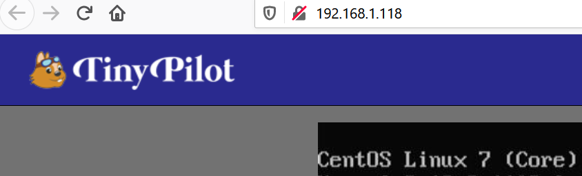
Cable and then turn-on the system you want to install. Then access the web-server of the Raspberry Pi via the TinyPilot URL via a Web-Browser like in the below example.
If it takes too long and the system is already up and running no worry just simply click <Control>+<Alt>+<Delete> on the virtual Keyboard to reboot the system again.
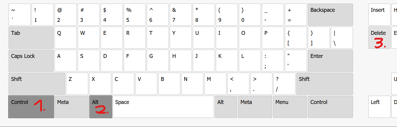
While the system boots now press the Key on the virtual Keyboard that will gain you access to the systems BIOS-Setup (<Delete> on many systems) until you are there like in the below example. Alternative try to get into the Boot-Selection Menu of the system.
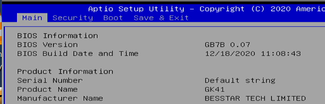
Depending on the BIOS figure out how to so a single PXE-Boot like in the below example. It is best practice to NOT to change the default booting first from local disk. Here is one example from one system. This will however be individual to yours.
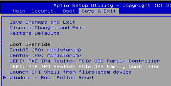
With this the installation process should start
Note
Installation time with sufficient Internet connection (as we download packets from public YUM-Repo Servers) lasts around 30minutes and the system will reboot two times during it.
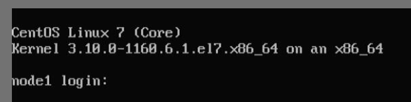
After the installation has been completed you should see something like this on the screen. Keep in mind that the 128T installer updates the Kernel.
Still on the Raspberry Pi about half way through the entire installation the OS-Installation will create local files in the /tftp directory. This is because we instructed the system to do that as Part of the kickstart file. This allows us to collect information from the system that we may (or may not) find very valuable later. See the examples below. It’s either sysinfo-<boot-IF-MAC> giving much info about the system itself or interfaces-<boot-IF-MAC> which has vary specific information about the the ethernet interfaces that you need later to turn it into a 128T SSR.
cd /tftp
ls -l
-rw-rw-rw- 1 tftp tftp   1391 Mar  5 11:00 interfaces-047d7b00ded0.txt
-rw-rw-rw- 1 tftp tftp   3026 Mar  5 09:14 interfaces-5c857e4840f3.txt
-rw-rw-rw- 1 tftp tftp   1924 Mar  4 21:42 interfaces-681def2462f7.txt
-rw-rw-rw- 1 tftp tftp   1491 Mar  5 12:27 interfaces-b8aeed704f57.txt
-rw-r--r-- 1 root root 911648 Mar  4 14:35 ipxe32.efi
-rw-r--r-- 1 root root 992896 Mar  4 22:53 ipxe64.efi
-rw-r--r-- 1 root root 331482 Mar  4 14:35 ipxe.pxe
-rwxr-xr-x 1 root root 122656 Mar  5 08:56 ldlinux.c32
-rwxr-xr-x 1 root root 123200 Mar  5 08:56 ldlinux.e32
-rwxr-xr-x 1 root root 139616 Mar  5 08:56 ldlinux.e64
-rwxr-xr-x 1 root root  23700 Mar  5 08:56 libutil.c32
-rwxr-xr-x 1 root root  32064 Mar  5 08:56 menu.c32
-rw-r--r-- 1 root root  46995 Mar  5 08:56 pxelinux.0
drwxr-xr-x 2 root root   4096 Mar  5 08:56 pxelinux.cfg
drwxr-xr-x 2 root root   4096 Mar  5 08:56 secure-boot
-rw-rw-rw- 1 tftp tftp  88969 Mar  5 11:00 sysinfo-047d7b00ded0.txt
-rw-rw-rw- 1 tftp tftp  98111 Mar  5 09:14 sysinfo-5c857e4840f3.txt
-rw-rw-rw- 1 tftp tftp 104119 Mar  4 21:42 sysinfo-681def2462f7.txt
-rw-rw-rw- 1 tftp tftp  91394 Mar  5 12:27 sysinfo-b8aeed704f57.txt
-rw-r--r-- 1 root root 197522 Mar  5 08:56 syslinux32.efi
-rw-r--r-- 1 root root 200992 Mar  5 08:56 syslinux64.efi
Here is an example on what’s reported in an interfaces- file
cat interfaces-047d7b00ded0.txt
Bootinterface: enp10s0
Router: router6
Node: node1
----next----
Interface: enp10s0
driver: atl1c
version: 1.0.1.1-NAPI
firmware-version:
expansion-rom-version:
bus-info: 0000:0a:00.0
supports-statistics: no
supports-test: no
supports-eeprom-access: yes
supports-register-dump: yes
supports-priv-flags: no
Permanent address: 04:7d:7b:00:de:d0
Settings for enp10s0:
        Supported ports: [ TP ]
        Supported link modes:   10baseT/Half 10baseT/Full
                                100baseT/Half 100baseT/Full
                                1000baseT/Full
        Supported pause frame use: No
        Supports auto-negotiation: Yes
        Supported FEC modes: Not reported
        Advertised link modes:  Not reported
        Advertised pause frame use: No
        Advertised auto-negotiation: Yes
        Advertised FEC modes: Not reported
        Speed: 1000Mb/s
        Duplex: Full
        Port: Twisted Pair
        PHYAD: 0
        Transceiver: internal
        Auto-negotiation: on
        MDI-X: Unknown
        Supports Wake-on: pg
        Wake-on: d
        Current message level: 0x0000003f (63)
                               drv probe link timer ifdown ifup
        Link detected: yes
----next----
Interface: wlp9s0
driver: ath9k
version: 3.10.0-862.el7.x86_64
firmware-version: N/A
expansion-rom-version:
bus-info: 0000:09:00.0
supports-statistics: yes
supports-test: no
supports-eeprom-access: no
supports-register-dump: no
supports-priv-flags: no
Permanent address: e0:ca:94:83:fb:5f
Settings for wlp9s0:
        Link detected: no
----next----
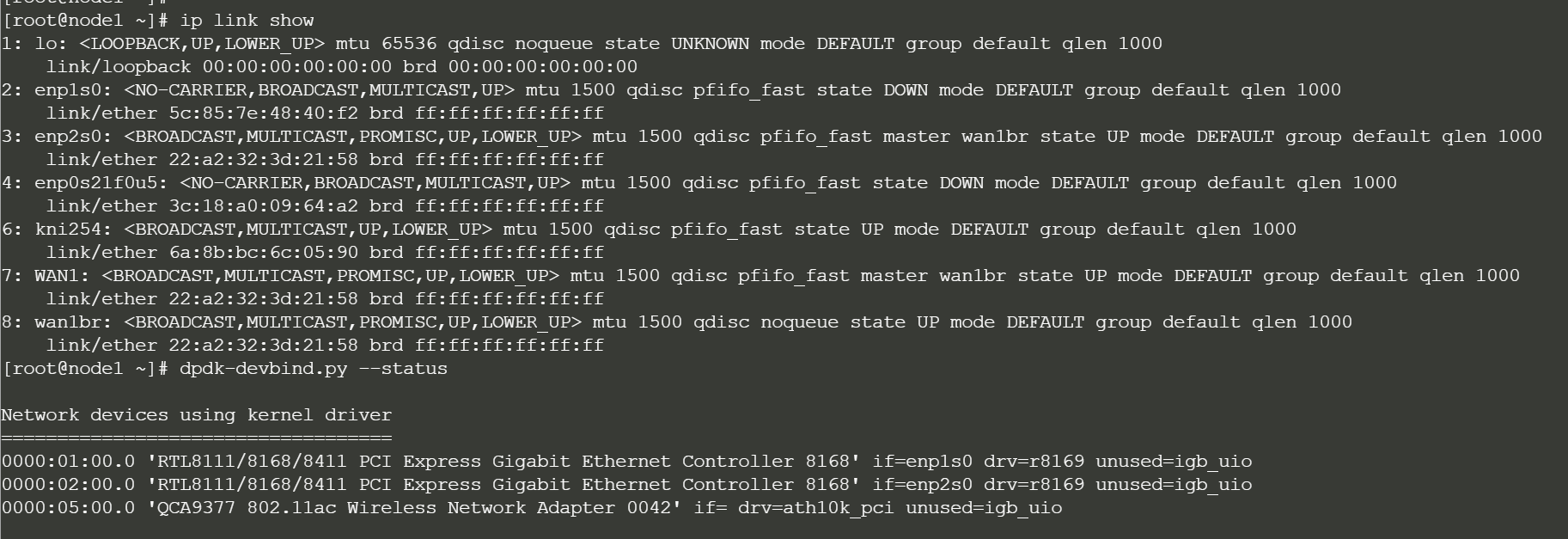
After the OS-Installation and after the 128T Software installation we send two messages to the Web-Server-Log by trying (but always getting a 404 error on purpose) to fetch some dummy-webpages. However, the GET messages themselves contain information about these systems we want to know really:
The first message as you see below always contains the IP-Address used during installation so you know how to SSH to the system later from the Raspberry Pi.
The first message then always contains the MAC-Address of the PXE-Boot interface. You can correlate that with the information in the /tftp directory.
The first message then always contains the PXE-Boot interface name. This informs you about later to use WAN-Interface names.
The first message also contains the router-name which you need to identify the Asset-ID you later see in the 128T Conductor.
The second Message (using the IP-Address of the sender to correlate it with the first message) tells you when the installation of the whole 128T Packages have been finished. The system should appear shortly after it reboted the second time on your 128T Conductor.
cat /var/log/nginx/access.log | grep 'Device\|128T'
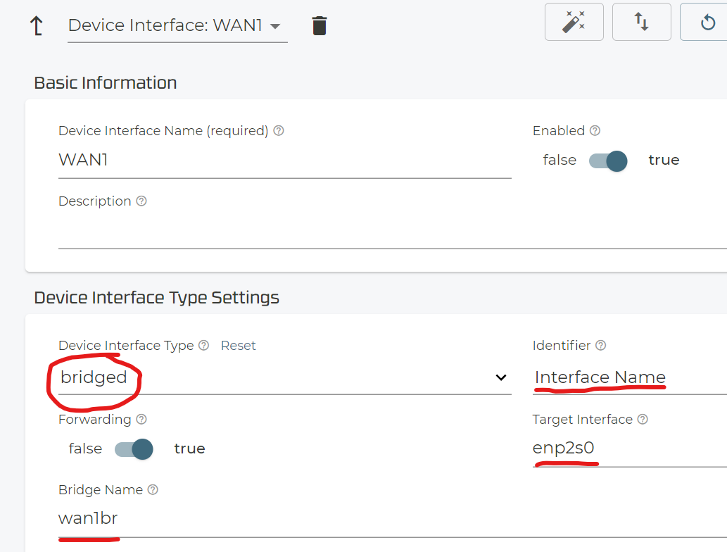
192.168.10.100 - - [05/Mar/2021:09:15:08 +0000] "GET /Device-ready-at-192.168.10.100-5c857e4840f3-enp2s0-router9 HTTP/1.1" 404 169 "-" "curl/7.29.0" "-"
192.168.10.100 - - [05/Mar/2021:09:29:06 +0000] "GET /128T-on-Router-INSTALLED HTTP/1.1" 404 169 "-" "curl/7.29.0" "-"
.
.
192.168.10.102 - - [05/Mar/2021:11:00:57 +0000] "GET /Device-ready-at-192.168.10.102-047d7b00ded0-enp10s0-router10 HTTP/1.1" 404 169 "-" "curl/7.29.0" "-"
192.168.10.102 - - [05/Mar/2021:11:11:06 +0000] "GET /128T-on-Router-INSTALLED HTTP/1.1" 404 169 "-" "curl/7.29.0" "-"
.
.
192.168.10.111 - - [05/Mar/2021:12:27:37 +0000] "GET /Device-ready-at-192.168.10.111-b8aeed704f57-eno1-router11 HTTP/1.1" 404 169 "-" "curl/7.29.0" "-"
192.168.10.111 - - [05/Mar/2021:12:40:47 +0000] "GET /128T-on-Router-INSTALLED HTTP/1.1" 404 169 "-" "curl/7.29.0" "-"
OPTIONAL before you consider to use the new system you just provisioned you should check if it meets the requirements. Remember we got a backdoor user to get root. So, from the Raspberry Pi just review the ARP-Table to find the IP-Address and the SSH to the system.
arp -an
? (192.168.10.115) at d2:30:bb:7e:ba:fb [ether] on eth0
? (192.168.1.7) at <incomplete> on wlan0
? (192.168.1.1) at a4:2b:b0:da:17:dd [ether] on wlan0
? (192.168.1.104) at 10:62:eb:92:4e:38 [ether] on wlan0
? (192.168.1.23) at 00:e9:3a:07:47:17 [ether] on wlan0
ssh juniper@192.168.10.115 (juniper123)
sudo -i
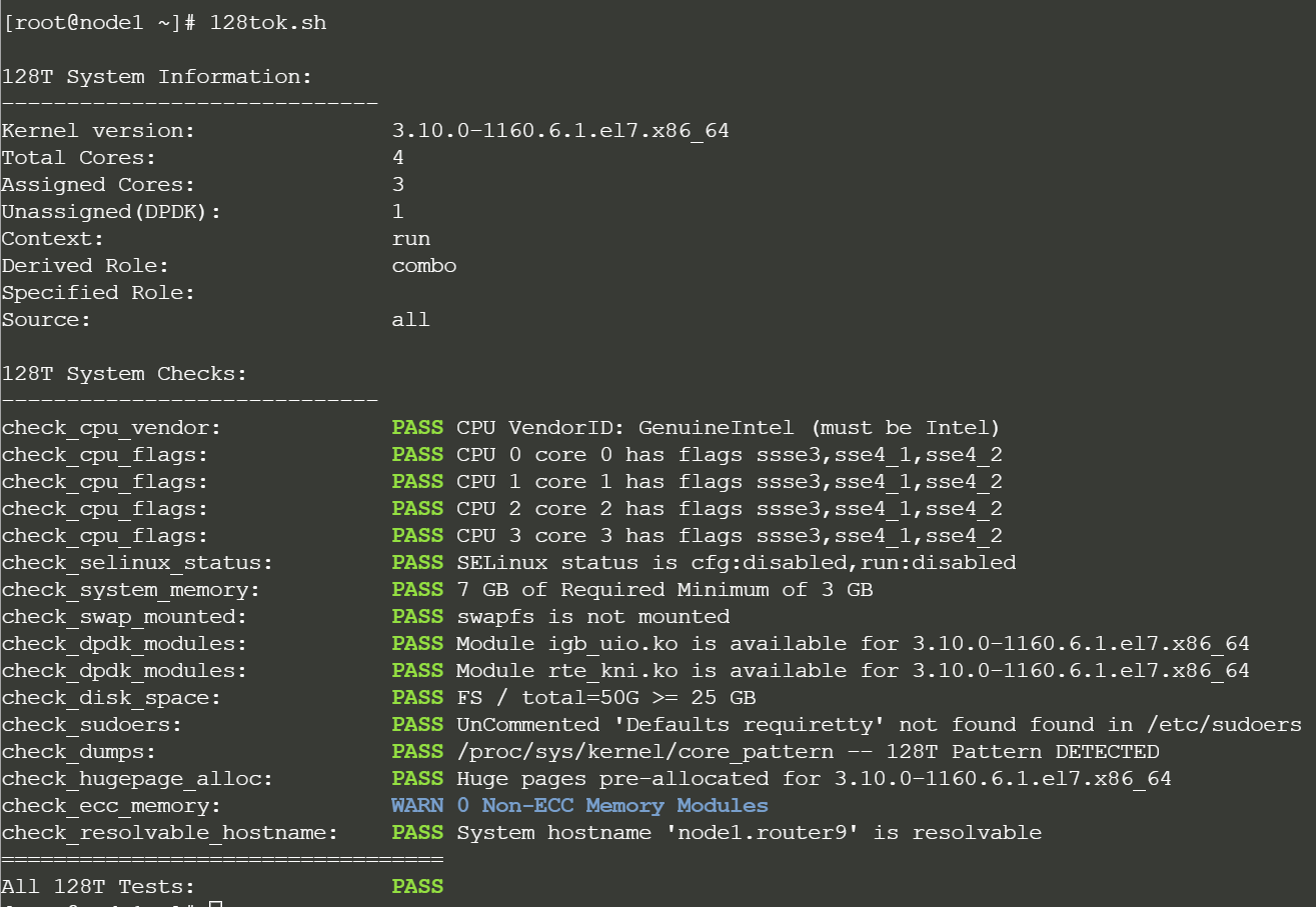
128tok.sh
.
# check the example output at the end of chapter 4.2.2
.
Note
Keep in mind that if you have configured as interface toward 128T this last step doesn’t work anymore as it’s no longer bound to the regular Linux Kernel-Space.
4.2. After installation on the 128T Conductor
Here are some guidelines on what to do on the 128T Conductor itself after the system installed and take over control finally to manage it from then on.
4.2.1. Activating the System on the 128T Conductor
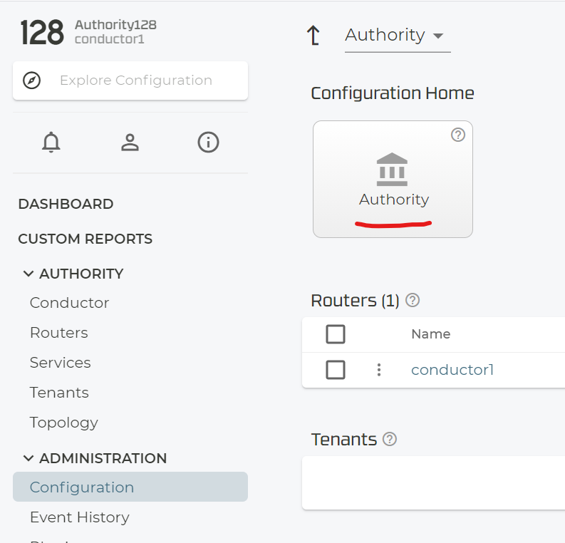
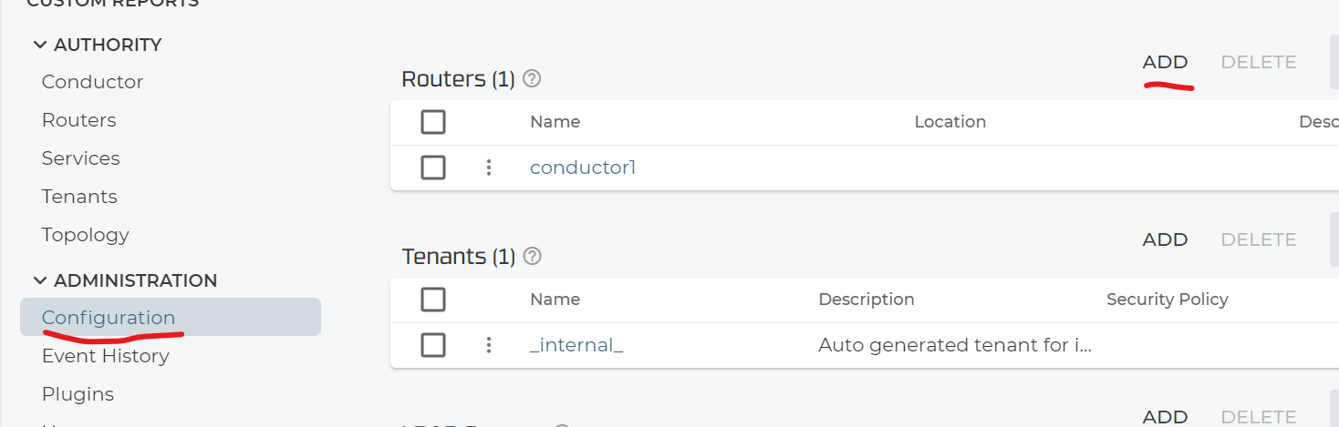
First (if not already done) access the Authority itself.
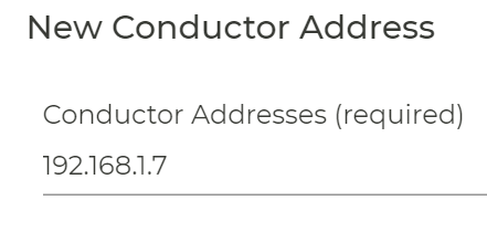
Add the external conductor IP-Address through this process.
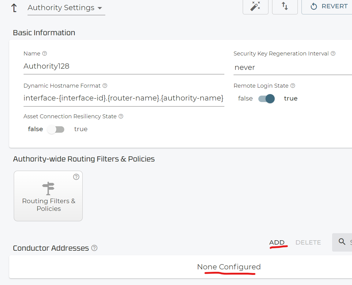
Again, the external (from the 128T side) visible IP-Address needs to be configured here.
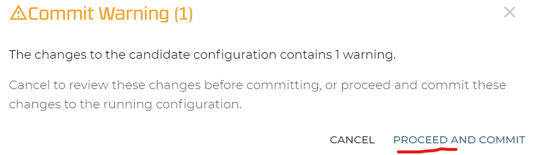
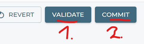
Validate and Commit your configuration.

All should be fine so really proceed.
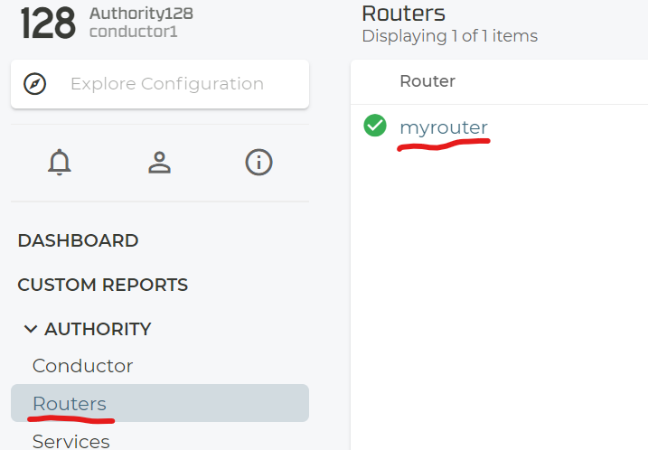
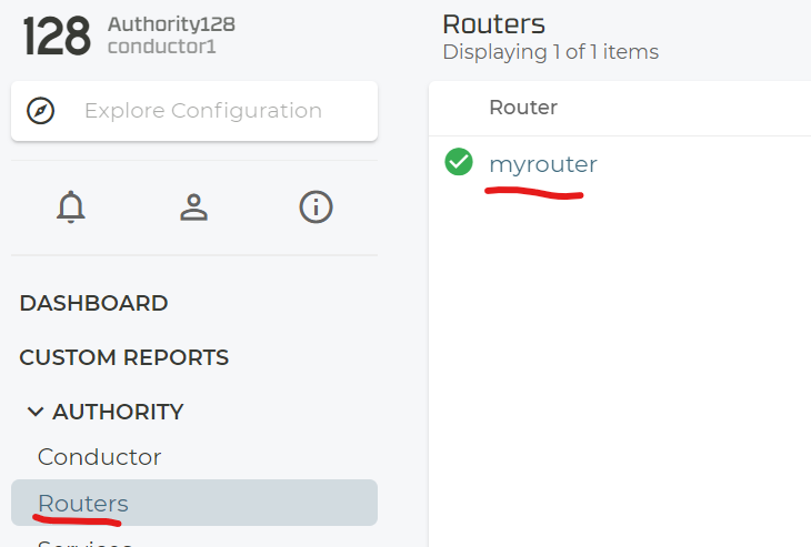
Now let’s create a new Router that we want to manage like this.
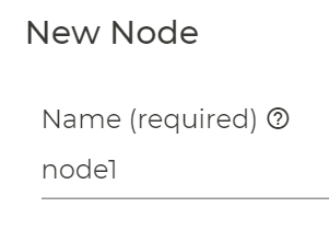
Give it a name.

Set an internal Policy like “internal” for now. You can change that later. Then add a new node.
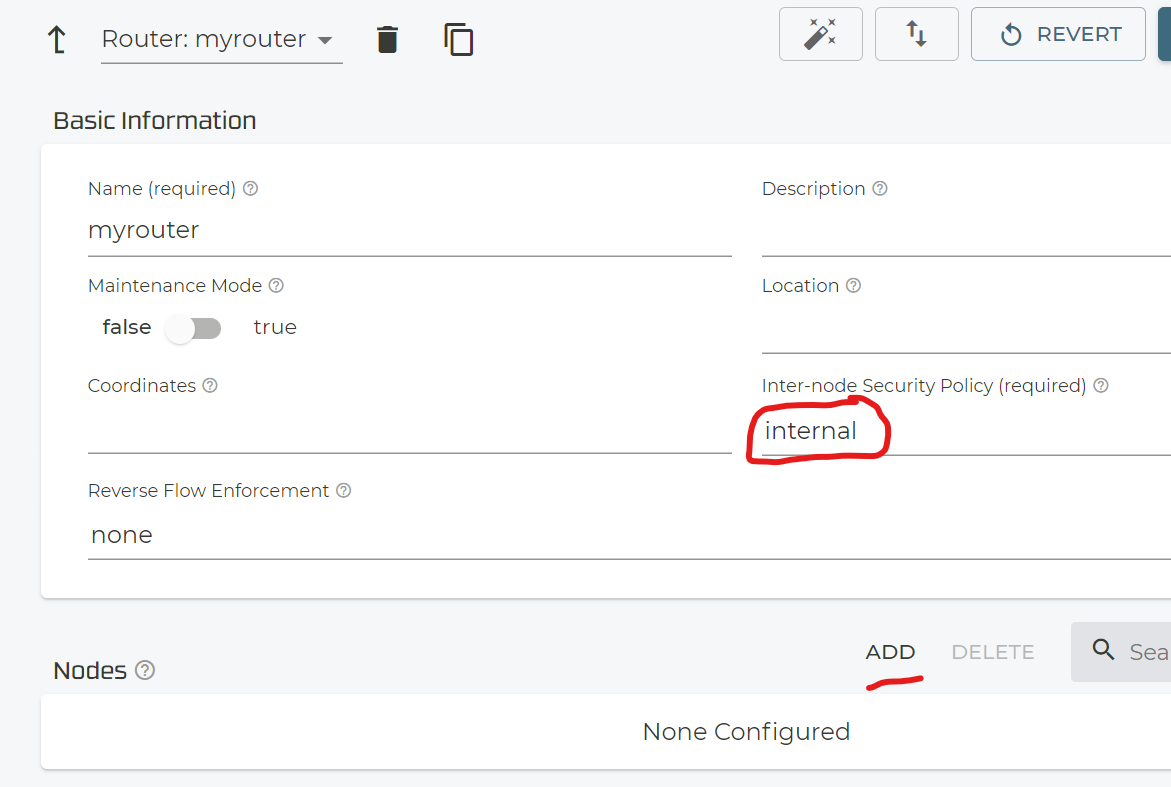
The usual node name is “node1” as convention.
Now based on the signaled Routers which you have installed you should see Associated Asset ID’s with the Router-names that where automatically created during the install process. Just select one you want to use now.
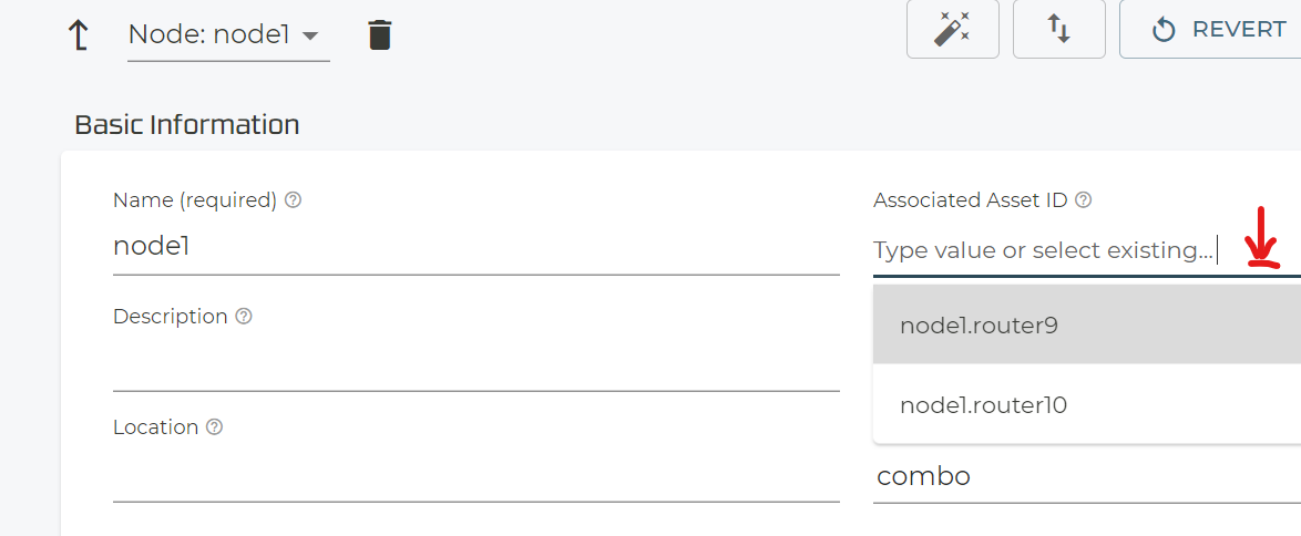
With your select Asset ID now select Role=combo.
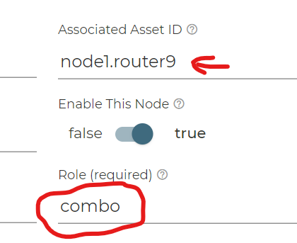
This is the minimal information you really need to provide so validate and commit your new system information.

We don’t know why but the above information may not be enough to get the Router managed in the Conductor. BUT we have a Trick for you to be used as well.
Either you create your first Interface like in chapter 4.2.2 based on the information send to the Raspberry Pi as in the /tftp/interfaces-<boot-IF-MAC> File found.
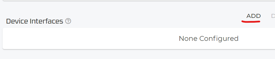
Or you use the approach below and create a dummy interface like below.
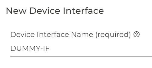
Just add a new Device Interface
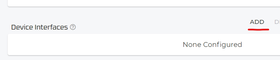
Give it the name ‘DUMMY-IF’ as it’s only temporary used.
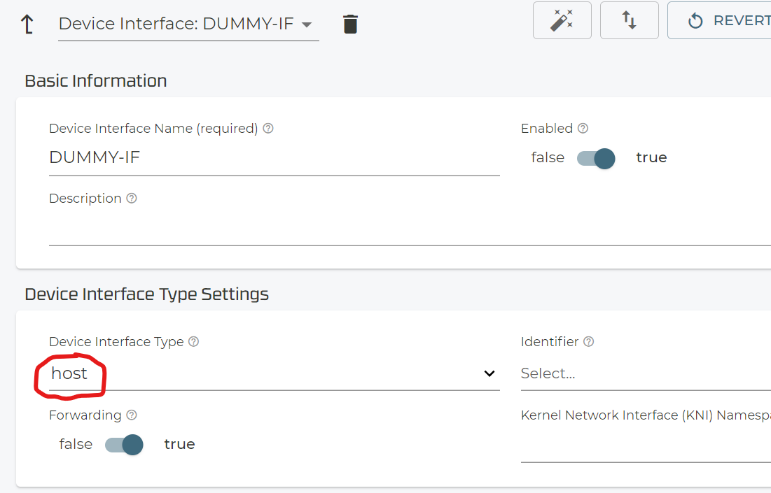
Configure only the Device Interface Type=host as below.
Validate and Commit again.
Now wait about 5minutes so that the 128T Conductor brought your new system under control. Then you can check your new system like the below.
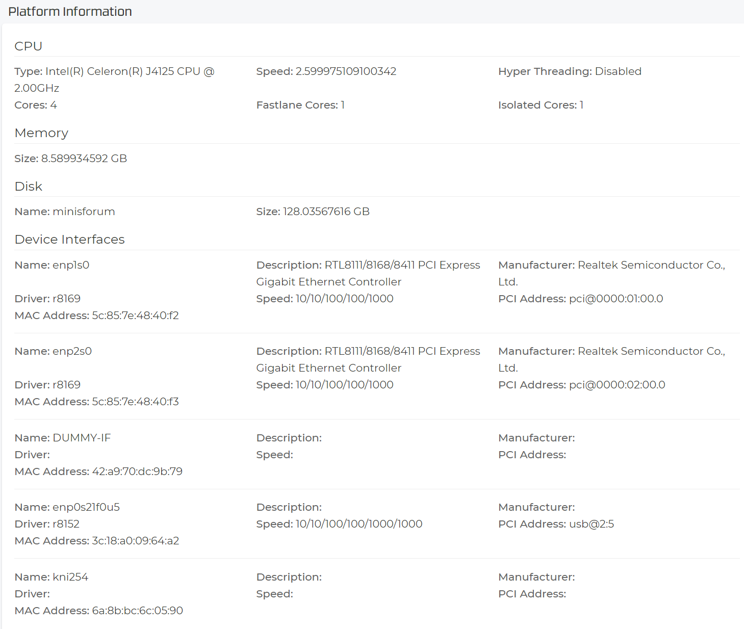
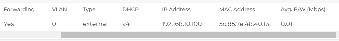
Select “Device Interfaces” and then the particular node.
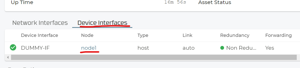
Now you see the information we wanted to really know from the device like Processor, Memory and all Interface information and so on. This has all the needed details again.
Note
Capture this screen for later! When you start to use interfaces, their detailed information disappears.
You do not need this interface anymore now so delete it.
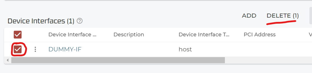
Do your Routine validation and commit to activate your changes.

4.2.2. Example of creating a WAN interface
After the system is now controlled via the conductor we can think about configuring the real WAN / LAN interfaces and do more. Usually you would use the PCI-ID to aquire an Device Interface. Our Lab system however did not have the recommended Intel NICs that should be there is you consider to use it in production. For a Lab where the system doesn’t have Ethernet Interface with more then 1Gbit/s the approach would then be to use the bridged type. As long as the Centos system has drivers for your NIC this will always work then. We also tested additional USB-to-Ethernet Dongles with this. But again this is NOT ADVISED FOR ANY PRODUCTION USAGE.
Note
Make sure you do not try a commit before we do it in this section else you may loose the system’s connection to the Conductor.
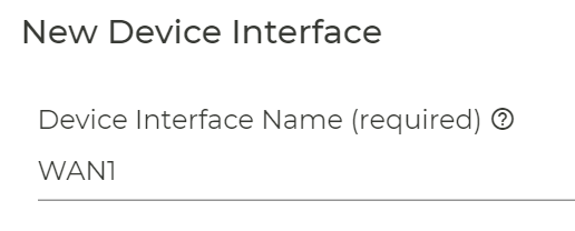
Add a new Device Interface to the node.
Give it a name.
This is what you need to configure as example to have the system using a bridged interface. The linux bridge itself (“wan1br” in this case) will be automatically created.
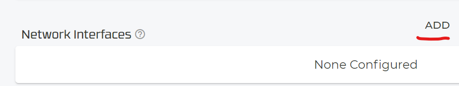
Then create a new network interface.
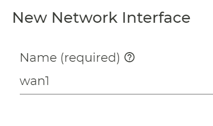
We recommend for all WAN Interfaces to set the switch Conductor=true . Else you may loose the connection to the conductor if this is the interface that has the OOB-communication to the conductor running at this moment in time. In our example we continue to expect getting a DHCP-Lease as the system is still behind the Raspberry Pi.
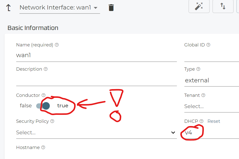
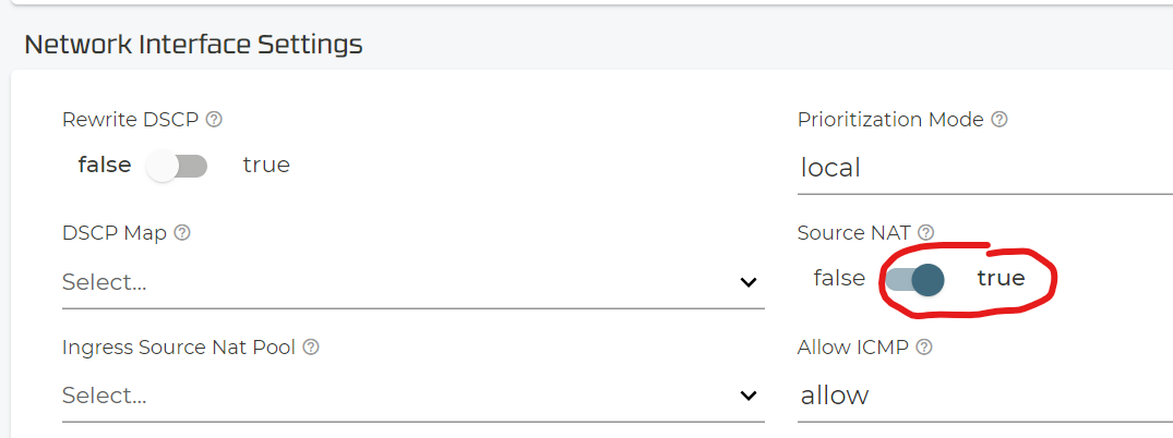
The switch to Conductor=true also requires to enable Source-NAT on the WAN-Interface to be enabled.
Now you can activate your changes.

Warning
Wait 5minutes for all the changes to happen and the 128T SSR connect back to the conductor!
Now we can check if all is OK again. Below are some uncommented examples of what you typically see.
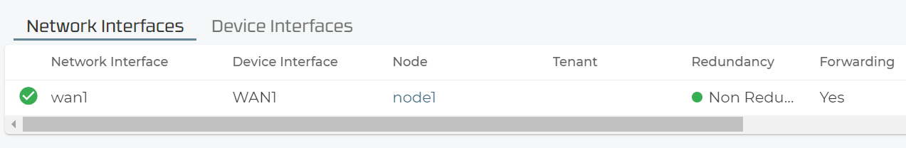
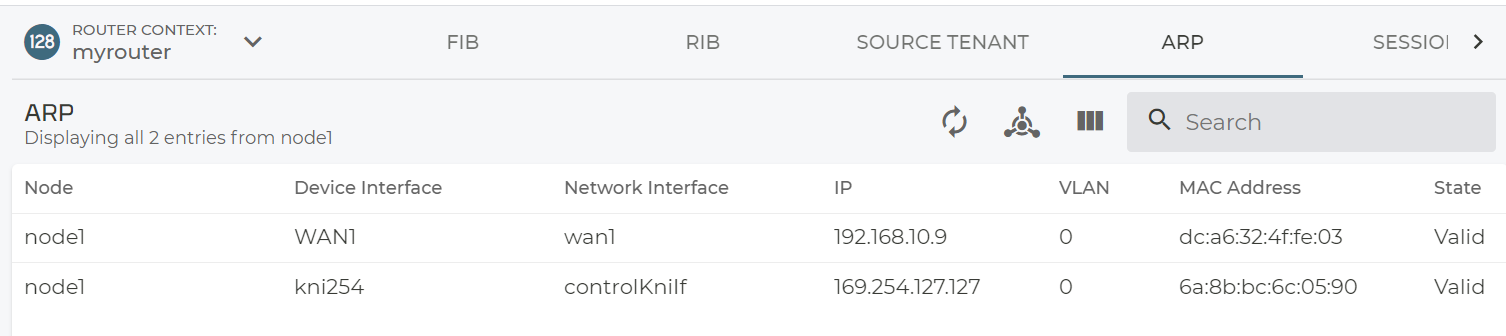
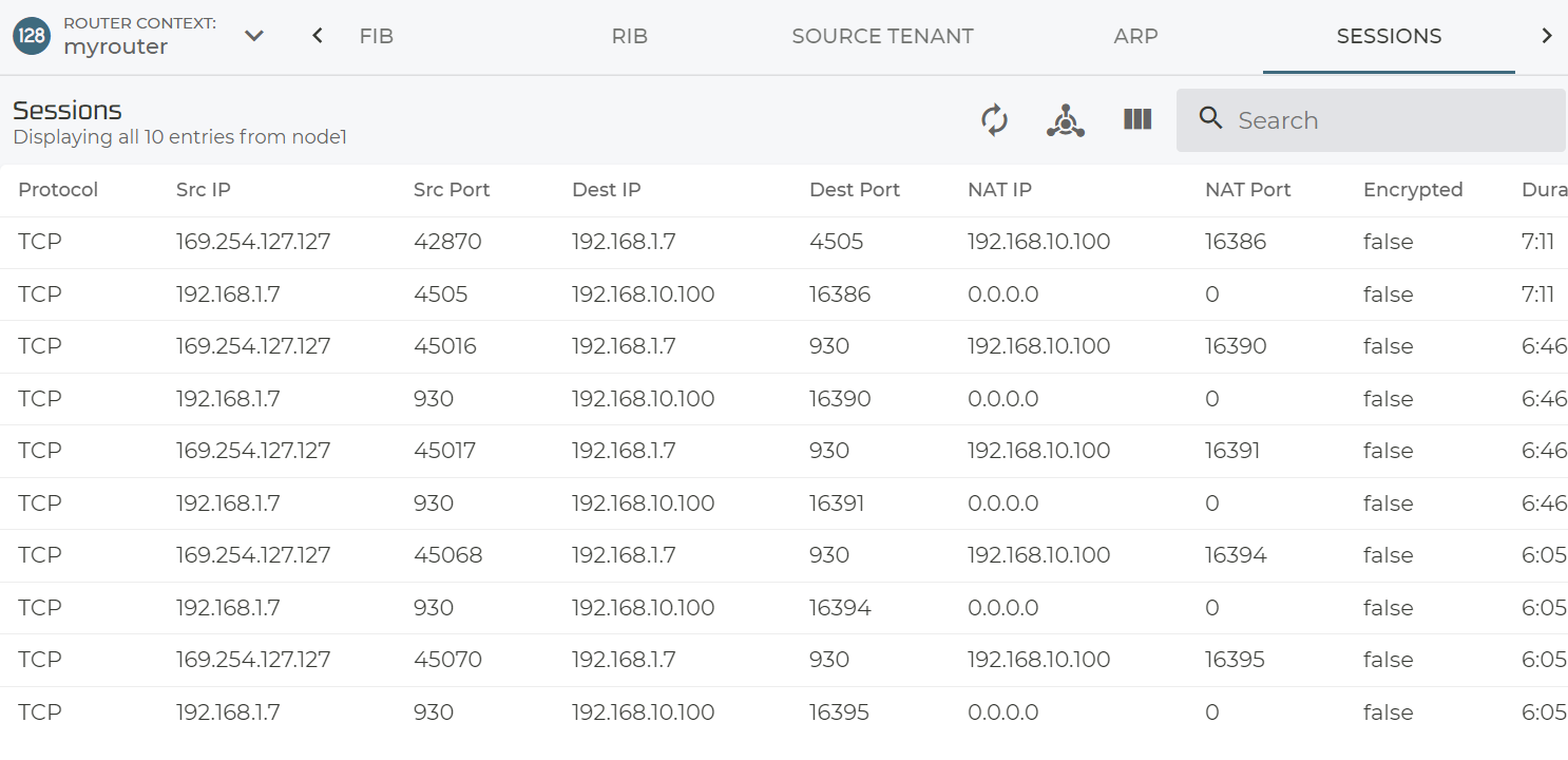
If you which to SSH to the system now please use the Conductor and either the juniper Backdoor use or admin to get to the PCLI.
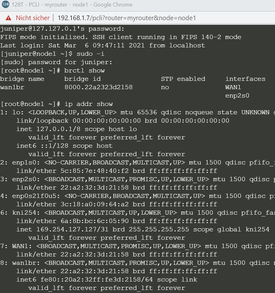
It always a tremendous debugging help executing the 128tok.sh script to figure if your system meets the minmal requirements.
Note
With this last Task executed you should be now fine to use it in a lab or send it to a site where the new Router will be used.
5. Additional stuff you may do
5.1. Add home-directory to root
I’m always using the default partitioning the Centos Anaconda kickstart does. Call it paranoia but I made my own experience in the past with customized partition-schemas that teached me this lesson. If you want you can modify the kickstart template with a customized partition yourself.
What I sometimes do is to change the partition on the fly. Reason is that this is a “server” and I don’t need a big /home for users on the system. I want that to be in the regular / partition so that all system services can use it. Here is what I do then.
arp -an
? (192.168.10.111) at b8:ae:ed:70:4f:57 [ether] on eth0
? (192.168.1.104) at 10:62:eb:92:4e:38 [ether] on wlan0
? (192.168.1.1) at a4:2b:b0:da:17:dd [ether] on wlan0
? (192.168.1.7) at <incomplete> on wlan0

ssh juniper@192.168.10.111

sudo -i

lsblk -io NAME,TYPE,SIZE,MOUNTPOINT,FSTYPE,MODEL
NAME            TYPE   SIZE MOUNTPOINT FSTYPE      MODEL
sda             disk 238.5G                        TS256GMSA370
|-sda1          part   200M /boot/efi  vfat
|-sda2          part     1G /boot      ext4
`-sda3          part 237.3G            LVM2_member
  |-centos-root lvm     50G /          ext4
  |-centos-swap lvm    7.8G [SWAP]     swap
  `-centos-home lvm  179.5G /home      ext4

# save the existing /home content
tar -czvf /root/home.tgz -C /home .

umount -fl /home
exit
exit

# you need to logout from ssh to not block the next process

ssh juniper@192.168.10.111
.
Could not chdir to home directory /home/juniper: No such file or directory

sudo -i

#yum install -y lvm2

lvremove -y /dev/mapper/centos-home
  Logical volume "home" successfully removed

lvextend -r -l+100%FREE /dev/mapper/centos-root

# restore the /home content so all is well again
tar -xzvf /root/home.tgz -C /home

lsblk -io NAME,TYPE,SIZE,MOUNTPOINT,FSTYPE,MODEL
NAME            TYPE   SIZE MOUNTPOINT FSTYPE      MODEL
sda             disk 238.5G                        TS256GMSA370
|-sda1          part   200M /boot/efi  vfat
|-sda2          part     1G /boot      ext4
`-sda3          part 237.3G            LVM2_member
  |-centos-root lvm  229.5G /          ext4
  `-centos-swap lvm    7.8G [SWAP]     swap
5.2. Building the USB-C OTG Cable to send Keyboard stokes to the Server (while powering the Raspberry Pi)
How to build the Cable itself is shown in very good video on YouTube here https://www.youtube.com/watch?v=uLuBuQUF61o .
As the Raspberry Pi 4 is powered through an USB-C Port do not try to solve the problem based on USB3. Your Keyboard is not fast anyway AND you have way more copper connections to measure out and connect as you see below.

This example USB-C Cable has a Shield, one red Power-wire, 4 other shielded wires plus 6 other wires so around 12 wires to maintain/connect. You need to tweak this issue into one that is better hand able for you as on USB2 you only deal with maximum of 5 wires (including the shield). The key piece to the solution is a USB-C to Micro-USB converter. Those are usually made to allow you using old USB2 Cables and Power supplies with newer Devices. Depending on how/where you buy they are around 2.-USD/EUR each. The ones I used are avail here. When you buy something make sure it meets two points:
It is confirmed/advertised you can power/load a Device attached to the USB-C Connector through the Micro USB port.
It is confirmed/advertised you can exchange data with devices attached through the (legacy) Micro-USB Port.
If the advertisement claims there is special electronics inside the converter like pull-up resistors and so on treat this as a good sign that you are buying the right gear. You can’t adapt from USB-C to USB2 just with connecting some wires. There is additional stuff/electronics needed.
Note
The issue usually can’t be solved through USB-C Hubs with OTG- Power capabilities. Depending on the Raspberry Pi 4 Version you have this may or may not work (also those are usually around 30.-USD/EUR). So better invest into a soldering-iron :-)
So always have the USB-C converter towards the Raspberry Pi 4 and then some Micro-USB cable powering the PI and emulating the Keyboard towards the Server we want to control.

Additionally, to build the OTG cable purchase/or have 2 * USB-A to Micro-USB cables like the ones found here. Then build the cable:
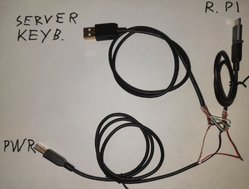
Here is a close-up of the cable. You just need to connect these wires (also showed in the video referenced above):

Outer Shield connects to: Keyboard + Power + Raspberry Pi 4
Black Ground wires connect to: Keyboard + Power + Raspberry Pi 4
Red +5Volt wires connect to: Power + Raspberry Pi 4
White USB-Data wires connect to: Keyboard + Raspberry Pi 4
Green USB-Data wires connect to: Keyboard + Raspberry Pi 4
You see this is now a very trivial issue to solve thanks to the USB-C to Micro USB converter AND you can reuse an old USB power device. Just make sure it emits 3 Amps / 5 Volts for the Raspberry Pi 4.
5.3. Adding Remote Power-Control
I’ve considered the add remote Power-Control in case the system hung-up in a way that only a power-cycle would solve this. There are some Wi-Fi controlled devices out there that speak MQTT like this one. However, I found that none of the cheap systems I had for Lab offer to be able to tell via a BIOS setting to automatically power-on after an external powerloss so I did not follow that route. I would also have to add some way of pushing the front power button via a kind of servo-motor controlled by the Raspberry Pi.
Warning
In a PRODUCTION environment make sure that the system/Router/Server is able to automatically boot after a power-outage!!!
5.4. VPN access to the Raspberry Pi
If you intend to send the P-Pi on site where you don’t have direct access to it via Wi-Fi then I suggest you install some sort of VPN Client software on it before you send it out. The VPN-Server can then be a simple VM running at a public Cloud service provider such as AWS / Azure etc. . This would solve the issue needing a public IP when the Raspberry Pi connects to the VPN-Server as well as you then using the same from you notebook to relay the traffic via the VPN-Server so that you can access the Raspberry Pi then through this Tunnel. I’ve done this in the past using simple OpenVPN software but other stuff like WireGuard may be good as well. Such a VPN-Server VM just costs around 20.-USD/month (excluding the traffic you send over it) but can be a tremendous help.
You may also consider using a Mobile connection to connect the Raspberry Pi to the Internet either by:
Adding an LTE Dongle via USB to the Raspberry Pi. Try to get newer Dongles that behave like a Ethernet-NIC via USB then the integration is quite simple.
Using a SmartPhone that offers a mobile Hotspot function so the Raspberry Pi uses normal Wi-Fi again.